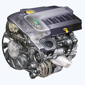
 The Td6 is a 3.0 litre, 6 cylinders, in-line direct injection engine having 4 valves per cylinder, controlled by a couple of overhead camshafts. The engine emissions assent to the ECD3 legislative obligations and utilize a catalytic converter, positive crankcase ventilation, electronic engine management control and exhaust gas recirculation to restrict the emission of contaminants. The unit is water-cooled and turbocharged. The fuel injection system features common-rail technology.
The cylinder block is of cast iron construction with a cast aluminium stiffening plate fastened to the base of the block to fine-tune the lower structure firmness. The cylinder head is cast aluminium with a moulded plastic camshaft cover. The single-piece oil sump is also cast aluminium.
The exhaust manifold is attached on the right side of the engine and a moulded plastic acoustic cover is fixed over the upper engine to decrease engine-produced noise. To lessen the level of transmitted engine vibration to the body of the vehicle, the engine is fixed on a couple of hydraulically damped mountings, fitted between the engine support brackets and engine sub-frame. These are regulated by the Engine Control Module (ECM).
The technical features include:
- In-line 6–cylinder engine with a cast iron crankcase
- Plastic cylinder head cover
- Light alloy cylinder head
- 4-valve technology with a centrally arranged fuel injector
- Valves and springs identical to the Td4
- Plastic manifold based on two-shell weld technology
- Exhaust turbocharger, with Variable Nozzle Turbine (VNT)
- Compression ratio of 18:1
- Common rail fuel injection system
- High-pressure fuel pump
- Cooling duct pistons with a central crown bowl
- Electronically controlled Exhaust Gas Recirculation (EGR)
- Exhaust re-treatment via a diesel specific oxidation catalytic converter and primary catalytic converter
- Switchable hydraulic engine mounts
- 7-blade cooling fan with viscous clutch drive
- Engine cut out begins at 4000 rpm. The cutout limit is reached at approx. 4800 rpm
Cylinder Block Components
The cylinder block components are described below:
Cylinder Block
The cylinders and crankcase are found in the cylinder block, which is made of single grey cast iron and having the hollow beam structure. The cylinders are direct bored. Oil is provided through lubrication jets for piston and gudgeon pin lubrication and cooling.
Lubrication oil is supplied throughout the block using the main oil gallery to vital moving parts through channels bored in the block which shift oil to the main bearings, and the higher-end bearings using holes machined into the crankshaft.
A tapping at the forward RH side of the cylinder block links a pipe to the turbocharger via a banjo connection. Oil under pressure from the oil pump is responsible for the lubrication of the turbocharger bearings.
Cylinder cooling is attained by coolant flowing using chambers in the engine block casting. NOTE: The water jacket does not possess core plugs. A couple of hollow metal bolts are utilized to detect the cylinder block to the cylinder head, one on every side at the front of the component.
A couple of supplementary hollow metal dowels are employed to identify the timing cover to the cylinder block. A port is involved at the back right-hand side of the cylinder block which attaches to the turbocharger oil drain pipe to carry back the lubrication oil to the sump.
A plug fastening the lubrication cross-drilling gallery is situated at the frontal right-hand side of the cylinder block. Plugs for the main lubrication gallery are incorporated at the front and back of the cylinder block.
Connecting Rods
The connecting rods are machined H-sectioned steel forgings. The big-end bearing shells are plain split halves. The upper half of the bearing shell is treated using the sputtering process (cathodic surface coating process) to increase its reluctance to wear.
The compact-end of the connecting rod has a bushed solid eye which is open to moving on the gudgeon pin. The tiny-end bush is a hand-push transition fit.
Pistons 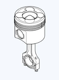
The six pistons are gravity die cast with graphite-compound layered aluminium alloy skirts. Be that as it may, the piston is identical to the one fixed to the Td4 engine. The lobe in the piston crown bowl is higher.
The combustion chamber is configured on a swirl chamber principle. The swirl chamber partly comprises the inlet air in the course of the combustion process and assists in offering turbulence for effective air/fuel mixture to support thorough combustion.
This decreases fuel ingestion, exhaust emission and smoke formed at full load. The four recesses in the piston's crown also offer clearance for the valve heads.
The pistons are fastened to the small-end of the connecting rods by fully variable gudgeon pins which are held in the piston by circlips. The pistons include an oil cooling channel for piston and gudgeon pin cooling, oil being delivered under pressure from the piston lubrication jets.
Piston Rings
Each piston is adjusted with a couple of compression rings and an oil control ring. The upper compression ring is positioned at a steel insert ring carrier which aids in providing a nominal reaction to compression forces.
The topmost ring is a 10° chromium-plated keystone ring. The 2nd compression ring is a tapered compression ring and the lowermost ring is a chromium-plated spring laden bevelled ring.
Piston Lubrication Jets
The six lubrication jets (one for each cylinder) have an extensive hook-type outlet and are fixed at the lowermost right hand side of each cylinder. The jets offer lubrication to the cylinder walls, and to the piston underskirt for cooling down the pistons and oiling the small-end bearings and gudgeon pins.
The input port to all lubrication jet couples with a port fitted in each mounting position tapped at the bottom of the cylinder block from a chief gallery on the RH side of the block.
Integrated Oil Cooler and Filter Assembly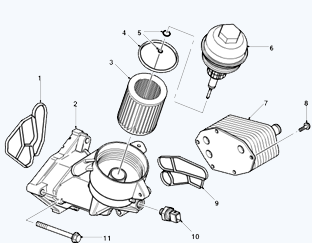
- Sealing gasket
- Filter housing
- Filter element
- O-ring seal – cap
- O-ring seal (2 off)
- Filter cap
- Heat exchanger
- Thermal exchanger to filter housing attachment bolt (Torx 3 off)
- Heat exchanger to filter housing gasket
- Oil pressure switch
- Filter cover to engine block attachment bolts 3 off
The oil filter housing contains an essential thermostatic valve which regulates the quantity of oil moving through the oil cooler, reliant on the oil temperature. Oil from the cylinder block moves through the oil filter housing and fractional flow is driven through the oil cooler before it is reverted to the cylinder block.
The coolant for the heat exchanger is provided directly from the crankcase. The oil pressure switch, running a warning lamp in the apparatus pack, is fixed to the oil filter housing.
Oil Pressure Switch
The oil pressure switch is placed in a port in the oil filter housing. If the oil pressure decreases to a particular value, the switch drives the warning lamp in the instrument pack.
High Pressure Fuel Pump
The high pressure fuel pump delivers fuel to the fuel rail and is attached to the edge on the front LH side of the cylinder block. The pump is a 3 radial piston type under the control of the EDC engine management system and it drives the chain from the crankshaft at 0.75 times the engine speed.
Crankshaft Position (CKP) Sensor
The crankshaft position (CKP) sensor is attached to the back LH side of the cylinder block. The sensor is an inductive type which deals with the reluctor on the flywheel.
Crankshaft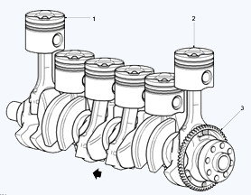
The crankshaft is made from high tensile steel. The bearing surfaces and radii are inductively strengthened for robustness and exhaustion resistance. It is maintained on 7 main bearings coupled with a flanged thrust bearing sited between No 5 and No 6 cylinders.
Dynamic balancing is attained by making use of the twelve balance weights. Cross-drillings in the crankshaft betwixt the adjacent main and big-end bearings are utilized to avert the lubrication oil to the big-end bearings.
Crankshafts are obtainable in three different sizes:
- Standard
- Undersize 1
- Undersize 2
Colour coding classifies the size of the journal. At the front of the crankshaft is a four-hole threaded construction, utilized to fasten the axially vibration damper and cooling fan. The engine RPM signal is caught from the reluctor “target” fixed to the crankshaft. The crankshaft oil seals are made from PTFE.
Main Bearings
The main crankshaft bearing shells possess oil channels and drilling in the higher bearing shell, to distribute oil by means of the crankshaft drillings to the adjoining rod big-end bearings.
Sump
The single-piece aluminium die-cast sump, with a central tunnel for the divergent drive shaft, is fastened to the lower crankcase extension by means of a rubber metal-backed gasket. The sump is bolted to the lower crankcase extension via 25 bolts. An oil deflector plate is connected to the crankcase reinforcing shell overhead the sump.
Oil Pump
The oil pump assembly is attached to the base of the cylinder block and is positioned in front of the engine block stiffener plate. The pump is an inner gear-type with sintered rotors and is operated by a chain and sprocket system from the crankshaft.
A pressure relief valve is added at the opening side of the oil pump to regulate oil pressure at higher engine speeds by recirculating oil via the relief valve back around the pump to the vent.
The spring and relief valve is a plunger type; when oil pressure is good enough to kick the plunger, oil is permitted to stream past the plunger to relieve pressure and hamper any more increase in pressure. Oil is distributed to the pump from the pick-up pipe, and the exit side of the oil pump supplies pressurised oil flow to the engine block chief oil delivery gallery.
Flywheel
Positioned between the engine and transmission, the flywheel is of sheet metal coated construction.
Camshaft Timing Components
Chain Drive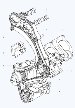
- Camshaft
- Guide rail
- Crankshaft
- Common rail high pressure pump
- Oil pump
- Tensioning rail
- Chain tensioner
Timing Case Cover
The timing chain cover is machined cast aluminium alloy and is attached to the cylinder block. Five bolts are applied to fix the upper flange of the timing cover to the cylinder head casting, and the other four bolts protect the head of the sump to the timing cover.
The base of the timing cover is situated at the forward face of the cylinder block by a couple of metal dowels. The front of the crankshaft travels across a hole in the timing cover, and a fungible beaded gasket is utilized to cover the interface betwixt the front of the crankshaft and the timing cover. The ancillary apparatuses and belt pulley attachments are attached to the front cover.
Chain Drive
A couple of timing chain drives are utilized. The timing chain amidst the fuel injection pump sprocket and the crankshaft sprocket is a simplex type. The timing chain is enclosed betwixt one fixed and one hydraulically modifiable tensioning rail.
The chain drive from the fuel injection pump sprocket to a couple of camshaft sprockets is to a simplex type. The chain is contained between one fixed guide rail and a hydraulically amendable tensioning rail to diminish chain flutter.
An extra plastic chain guide is placed overhead the two camshaft sprockets. The modifiable tensioning rails are of aluminium die-casting construction having clip-fastened plastic slide linings. The static guide rails are shaped plastic.
The tensioner rails are connected to the front of the cylinder blocks by making use of the pivot bolts which enable the tensioner rail to rotate about its axis. The spring tensioner for both chains is given by a single unit which comprises dual spring operated, hydraulically damped plungers that function on the tensioning rails at the hanging side of each of the timing chains.
Compressed oil for the adjuster is delivered through the rear of the unit via an oil supply port at the head of the cylinder block. The sideways movement in the tensioner arm leads the timing chain to tension and as a result, compensation for the timing chain wear and the chain flutter is spontaneously regulated.
The timing chains are oil splash oiled via the oil pump and chain tensioner. Oil spray is pointed to the chain from numerous oil supply ports in the front of the cylinder head and cylinder block. An added chain from the crankshaft sprocket attaches to the oil pump sprocket for oil pump process.
Cylinder Head Components
Cylinder Head
Although the Td6 is of an in-line arrangement, its cylinders are organised into two sets of three. The forward set comprises of cylinders 1 to 3 and the tail bank incorporates cylinders 4 to 6. The cylinder head is of aluminium gravity die casting structure. The cylinder head is attached to the cylinder block via M12 cylinder head bolts organised underneath each camshaft.
The aluminium cylinder head contains the chain-driven overhead camshafts, fuel injectors, glow plugs and valve gear. The TD 6 engine has a 4 valve configuration, identical to the TD 4. There are a couple of exhaust ports joined in the cylinder head, a swirl inlet and a tangential inlet port.
The common fuel injector rail is centrally arranged with the glow plug fixed to the inlet side. Coolant flow goes into the head from the exhaust side and makes the exit through No 3 and No 4 cylinder, the vent side to the heater matrix and radiator. The Engine Coolant Temperature (ECT) sensor is bolted into an aperture at the back LH side of the cylinder head.
Cylinder Head Cover
The plastic constructed cylinder head cover is applied to cordon off the oil chamber in the cylinder head. It protects oil spray from the camshaft and the chain drive gear and serves as a cover for the valve gear.
An oil separator for the crankcase aeration system is attached at the head of the cover. This delivers preliminary oil separation by cyclone and fine separation by making use of an internal yarn wrap.
The separator unit also encompasses a pressure control valve. The camshaft cover includes an integrated air filter housing which is de-coupled from the cylinder head to absorb and minimise the transmission of engine noise. The camshaft cover also provides a mounting for the mass air flow (MAF) sensor.
Cylinder Head Gasket
The multi-layer steel cylinder head gasket has cylinder specific water flow cross sections for uniform coolant flow. There are three thicknesses of gasket presented, singled out in accordance with the determined piston clearance.
The width of the gasket is determined by the sum of identification holes, one hole being the slimmest and three holes being the widest.
Vacuum Pump
The vacuum pump is positioned on a support bracket at the forward RH side of the cylinder head and is regulated from the exhaust camshaft.
Camshafts
There are a couple of camshafts including exhaust (right) and intake (left). Each camshaft is kept in place by seven bearing caps. Each bearing cap is mounted to the cylinder head by a couple of bolts. The camshafts are manufactured using the clear chill casting procedure and are hollow cast.
The cam lobes have a minus cam radius. The camshafts are regulated from the crankshaft by means of a simple chain and sprocket configuration. Each camshaft has a dozen machined lobes for running the inlet and exhaust valves via lash adjusters and roller type finger levers.
Inlet and Exhaust Valves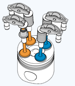
The inlet and exhaust valves are same and feature floor, solid one-piece head, and stem crafted from Nimonic alloy material. The valve springs are crafted from spring metallic and are of the parallel single-coil type.
The bottom of each spring rests at the flange of a spring retainer which has a crucial valve stem seal. The top end of the spring is fitted through a spring retainer that's held in the top stop of the valve stem by split taper collets.
The taper collets have grooves on the inner bore that discover to grooves ground into the top stems of the valves. Valve seats and valve guides are an interference match inside the cylinder head.
Hydraulic Lash Adjusters and Roller Finger Rockers
The valves are operated through curler-type finger rockers and hydraulic lash adjusters, actuated through the camshaft lobes. While the camshaft lobe pushes down on the peak of a finger rocker, curler mechanism, the respective valve is compelled down, opening the affected inlet or exhaust port.
Using this sort of actuation approach helps lessen friction inside the valve timing mechanism. The frame of the hydraulic lash adjusters includes a plunger and two chambers for oil feed and pressurised oil.
The pressurised oil is supplied to the lash adjusters through the primary oil galleries inside the cylinder head and through a hole in the aspect of the lash adjuster frame. The oil passes right into a feed chamber inside the lash adjuster and then through a discrete strain chamber by a one manner ball valve.
Oil flow from the pressure chamber is dogged by dint of the quantity of clearance among the lash adjuster outer frame and the centre plunger. Oil escapes up the side of the plunger each time the lash adjuster is wrought, the downward stress at the plunger forcing an equivalent amount of oil within the lash adjuster frame to be displaced.
When the downward pressure from the camshaft and finger rocker is eliminated (i.e. after the trailing flank of the camshaft lobe has exceeded), oil pressure forces the lash adjuster's plunger up once more. This pressure isn't enough to effect the valve operation, but removes the clearance among the finger rocker and pinnacle of the valve stem.
Electronic Fuel Injectors
There are six digital gasoline injectors (one for each cylinder), each placed inside the centre of a cylinder's four valves. The electronic gasoline injectors are provided with fuel from the gasoline rail and supply finely atomised fuel at once into the gas chambers.
Ancillary Components and Belt Drives
The ancillary additives, which comprise the torsional vibration damper, alternator, A/C compressor, steerage pump and water pump, are compelled by the engine crankshaft through the ancillary pressure belts.
The belts, which are upkeep free poly-V kind belts, are mechanically pre-loaded by way of the tensioning rollers and are routed over deflection pulleys for you to maintain enough adhesion about the drive wheels. This ensures slip loose pressure of the ancillary components.
Belt Drive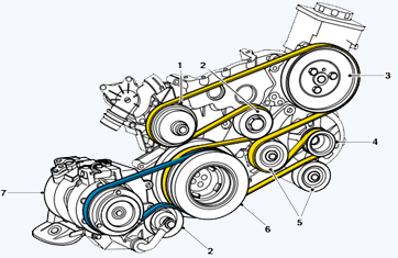
- Water pump
- Tensioning pulley
- Power steering pump
- Alternator pulley
- Idler pulley
- Torsional vibration damper
- A/C compressor
Torsional Vibration Damper
The torsional vibration damper with decoupled belt pulley suppresses longitudinal vibration and decreases noise. It’s far mounted to the forward quit of the crankshaft with four important bolts torque loaded to forty five Nm.
Tensioning Pulley
The tensioning pulley or idler pulley is a spring-biased component.
Lubrication
The lubrication gadget is a wet sump, pressure fed nature. It lubricates the engine sliding surfaces, dissipates heat, absorbs fuel combustion residue and seals off the space between the cylinder and piston.
Lubrication Circuit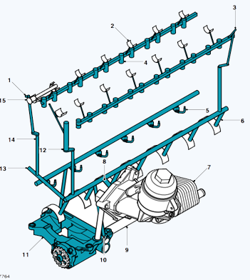
- Pressure supply to upper chain lubrication
- Camshaft bearing
- Run out stop – Hydraulic Valve Adjuster gallery
- Hydraulic valve lash adjuster gallery (HVA)
- Piston spray nozzle — hook-type nozzle
- Cylinder block main oil gallery feed for crankshaft bearings
- Oil filter with oil cooler
- Oil gallery next to oil filter — core oil gallery
- Oil intake pipe
- Unfiltered oil duct
- Oil pump
- Pressure supply for upper chain lubrication
- Pressure supply to Turbo-charger
- Riser to cylinder head
- Pressure supply to vacuum pump
Operation
Oil from the sump is drawn up thru a fabricated metal pipe which contains a mesh to filter out any surprisingly big portions of material that can purpose harm to the oil pump. The pinnacle of the pick-up is centrally engrossed within the sump oil that's added to the inlet facet of the eccentric rotary pump.
The oil pump is pushed from the crankshaft by means of a sequence and sprocket gadget. Pressurised oil from the pump is handed through a port within the bottom of the cylinder block and is directed up to the oil inlet port of the oil cooler and filter housing via a port within the RH aspect of the cylinder block.
The oil pump incorporates an oil pressure remedy valve which opens to permit oil to be recirculated around the pump if the oil stress increases to sufficient high degree.
The inlet port of the oil cooler and filter housing has a quintessential non-return valve which let it to circulate into the filter, but thwarts unfiltered oil draining back out of the filter housing when oil pressure is being reduced.
The oil passes via the oil filter unit and out to the oil cooler. The percentage of oil drift exceeded through to the oil cooler is dependent on a thermostatic by-pass valve that's integrated into the oil filter housing.
A boom in oil temperature causes the by-pass valve to open and permit a more percentage of oil flow to be directed thru the oil cooler. The remainder of the oil waft from the whole aspect of the filter out element is directed to the opening port of the oil filter housing wherein it combines with the oil float being returned from the oil cooler earlier than being passed back into the cylinder block.
An oil strain transfer is protected within the outlet port of the oil filter housing to feel the oil pressure level before the oil drift enters the primary oil gallery within the engine block. A caution lamp inside the tool percent is switched on if the oil pressure is detected to be too low.
Oil coming into the cylinder block core gallery passes via drillings to the crankshaft fundamental bearings and cross drillings within the crankshaft direct oil to the head bearings. An extra 4 drillings in the cylinder block deliver oil at reduced pressure to the lubrication jets for piston and cylinder cooling and gudgeoned pin lubrication.
A cross channel from the LH primary oil gallery crosses to the RH side of the cylinder block where there is an outlet port which gives a pressurised oil deliver to the turbocharger bearings via a banjo connection and outside piping.
Riser channels at the front RH aspect and rear LH aspect of the cylinder block are used to channel oil to mating ports in the cylinder head and provide a source for cylinder head lubrication and working pressure for the lash adjusters.
Oil is fed through oil galleries on the LH and RH facet of the engine and six cross channels from every gallery directs oil to the camshaft bearings. Lubrication oil fed to the lash adjusters passes up via the lash adjuster's frame to the finger rockers for lubrication of the surfaces among the finger rockers and the camshaft lobes.
Tapered plugs seal the cylinder head oil galleries at the rear of the cylinder head, and a further tapered plug is included in the cylinder head on the front of the RH gallery. An extra riser channel from the cylinder block LH chief oil gallery is used to deliver lubrication to the timing chain system through numerous outlet ports at the front of the cylinder block and cylinder head.
Engine Mounts System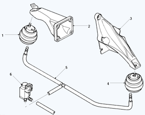
- Right hydraulic damper
- Right engine mounting
- Left engine mounting
- Left hydraulic damper
- Vacuum supply pipe
- Engine mount damping control actuator
A couple of hydraulically inhibited engine mounts are put in position between the engine support brackets and engine sub-frame to minimize the level of transmitted engine vibration and noise.
The damping specificities of the mounts are regulated by controlling the rate of hydraulic fluid transfer between two internal chambers.
The system comprises a couple of hydraulic mounts, coupled with variable damping controlled by a vacuum, a control actuator, electric and vacuum lines.
The vacuum, regulated by the electrical control actuator, is delivered through a distributor in the vacuum line betwixt the vacuum pump and brake booster. The system is regulated by the EDC System.
Hydraulic Engine Mount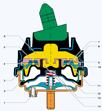
- Vacuum connection
- Bellows
- Nozzle
- Annular channel
- Diaphragm
- Upper hydraulic chamber
- Orifice
- Upper nozzle plate
- Nozzle
- Lower nozzle plate
- Lower hydraulic chamber
- Support cup
- Spring
- Channel
By applying a vacuum, the Engine Control Module (ECM) controls the engine damping mounting in two stages:
“Hard” Engine Mount
When it comes to the basic setting, no vacuum is exerted on the hydraulic mount. The spring deals with the support cup to shut the U-bellows against the upper nozzle plate. Hydraulic fluid moves from the upper hydraulic chamber through the nozzle, the annular channel and via nozzle into the lower hydraulic chamber. The annular channel extends over approximately 300 degrees.
Because of the length of the annular channel and the minor nozzle opening, the hydraulic oil streams between the upper and lower hydraulic chamber only in the case of vibrations up to the natural frequency of the engine (around. 10 Hz), thus creating a vibration absorber effect.
At greater frequencies, the equalisation between the hydraulic chambers is hindered by the length of the annular channel and the tiny nozzle vents. From the practical point of view, the equalisation between the upper and lower hydraulic chamber does not occur. Diaphragms are fitted in the holes of the nozzle plates in order to achieve good acoustic characteristics at high frequencies with small amplitude.
"Soft" Engine Mount
In idle mode and in the speed range near to idling, the spring is pulled down by exerting vacuum at vacuum connection. The channel in the centre of the upper nozzle plate now acts as a bypass between the upper and lower hydraulic chamber. This enables the hydraulic fluid to move evenly betwixt the upper and lower chambers. The rise in the fluid flow rate softens the damping action of the hydraulic mount, reducing the dynamic rigidity of the engine mount.
EDC Parameters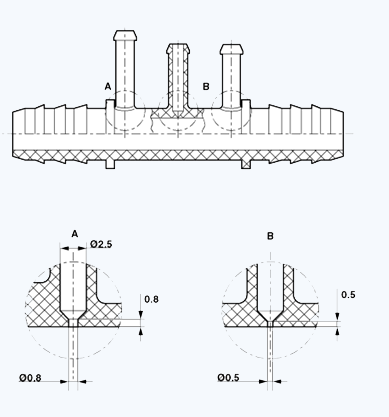
The ECM regulates the engine mounts hinged on the following parameters: Switching Value Engine Speed 900 RPM Vehicle speed 60 km/h (36 MPH).
Vacuum Supply Distributor
The vacuum required to activate the engine mounts is attained via a distributor situated in the vacuum line amid the vacuum pump and brake booster.
For this purpose, the vacuum line of the damping-regulated hydraulic mount is attached to the long vent of the distributor.
The vacuum differs within the pressure range from 0.5 to 0.9 bar. It is switched by means of a damping control actuator.