While the first Land Rover was sketched on a sand beach in wales, the technical evolution has taken giant leaps since its inception. Today, Land Rover V8 engines are some of the best and technically advanced engines ever to be used in any 4x4.
If you are looking for the replacement of your Land rover V8 engine then you have landed at the right place as Royal Rebuilds is your best one stop solution to get the engine replacement done and if by any chance we do not have the required engine available, then we promise to get your existing engine rebuild to the highest standards. You can complete the whole process from the safety of your home.
Large stock of Land Rover V8 Engines Available
We have a vast network through which we acquire robust working Land Rover V8 engines from all over UK. Our engines are run tested and compression tested for ultimate performance. If by any chance, we are not able to provide the required engine for replacement. We promise to rebuild your existing engine to the highest standards.
Engine Replacement Experts at Your Service
We have years of experience under our belt to either replace the Land Rover V8 engines or rebuilding your existing engine. Our expert and experienced mechanics can get the task done in no time. They have extensive experience under their belt for engine replacements and engine rebuild.
State of the Art Workshop
Over the years we have built the workshop that is specially built for the engine replacements or rebuilds. We have brought the latest equipment and for our experienced staff it has become second nature to replace or rebuild the Land Rover V8 engines. We have made it our mission to help the customers in need and make every possible effort to keep the charges minimal so the process is affordable for everyone.
Satisfied Customers and Tremendous Savings
We aim to provide 100% customer satisfaction to our clients by offering them warranty of every engine that is being replaced or rebuild by us depending on the condition of the engine. A customer’s confidence grows when they know that they can claim the warranty if things go south. You can save up to 50% when you decide to buy used or refurbished engine from us instead of a new engine. our festive sales can add extra 10%.
We Offer Delivery and Fitting Service
What if you do not have enough time to go through the whole process? Worry not. We are here to help you out. Up to a reasonable distance, we can arrange a pickup of your vehicle where ever it is parked. We get the replacement or rebuild job done and bring it back to you asap. Or we can deliver your engine at your address with a fast and reliable delivery service.
The V8 Land Rover engine, in general, is a 4.4 litre, water-cooled engine with eight cylinders (two banks of four cylinders arranged perpendicular to each other) and four valves per cylinder. The engine emissions go along with the ECD3 (European Commission Directive) and NAS LEV 2 legislative requirements. The engine incorporates five main castings consisting of two cylinder heads, a cylinder block, a timing cover and an oil sump, all of which are made from aluminium alloy.
Plastic rocker covers are placed on the cylinder heads and, betwixt the cylinder heads, there lies a plastic manifold inlet assembly. A plastic moulded acoustic cover is fitted to the front side of the engine to reduce the level of noise coming out of the engine. The engine is supported, between cast mounting brackets and the front subframe, on a couple of separate hydraulically damped mounts.
Technical Features
• Four valves for each cylinder
• Only one plenum chamber
• Variable Camshaft Control (VCC) system
• Double roller timing chain
• Hydraulic Valve Adjusters (HVA)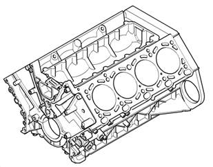
• Water Cooled Oil Cooler
Engine specifications
The specifications of the engine are listed below
Engine type 90° V
Cylinders 8
Stroke/bore 82.7/92.0 mm
Displacement 4398 cm
Peak Torque 440 Nm (324 lbf.ft) @ 3600 rev/min
The compression ratio of 10: 1
Highest Power 210 kW (285 PS; 282 bhp) @ 5400
Rev/min
Firing order 1–5–4–8–6–3–7–2
Crankcase
Most of the automakers use Alusil to make Crankcase to decrease the deficiency of engines because the fuel oils owe a high sulphur fuel. The cylinder barrels hold a nickel dispersion coating (Nikasil) and are finished by polishing only. On the left side of the crankcase, there is an adaptor plate that is responsible for the feed and returns flexible pipes to the oil filter assembly. The water drain plug is also fitted at the lower LH back corner to drain out the coolant from the crankcase.
Crankcase Ventilation
The crankcase ventilation system is pressure regulated by a valve fixed at the back of the intake manifold. Vacuum supply ports are fixed on the valve for the power brake booster and the fuel pressure regulator. The pressure regulating vent valve alters the vacuum applied to the crankcase depending on engine load. The valve is well-adjusted betwixt spring pressure and the volume of manifold vacuum. At idle when the vacuum is high, the valve closes down and only allows a small number of blow-by vapours to pass into the manifold.
At part to full load conditions, the spring unbolts the valve and the added blow-by gasses moves into the manifold. An additional tube leads the blow-by gasses through the manifold and up to the mixing plate. The crankcase ventilation system is completely sealed. Hose clamps are used at all connections to ensure that the system does not contain any leaks. The crankcase ventilation system uses a cyclone separator to purge the blow-by gasses of any oil vapours. The oil vapours condense in the separator and drain back into the sump.
Crankcase Ventilation System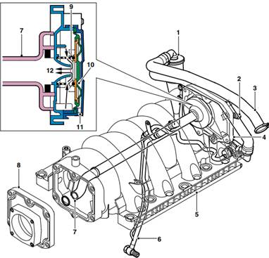
1 Oil separator
2 Breather hose, the oil separator to vent valve
3 Breather hose, LH camshaft cover to oil separator
4 Inlet manifold cover and vent valve
5 Inlet manifold
6 Oil drain pipe assembly
7 Inlet manifold vacuum pipe
8 Mixing plate
9 Vent valve spring
10 Vent valve diaphragm
11 Atmospheric vent
12 Blow-by gasses
Crankshaft
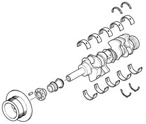 The crankshaft is manufactured from forged steel with five main bearings and the thrust bearing on number five bearing. Six counterweights fitted. These are positioned in harmony with the ignition firing order to ensure smooth running. The crankpins are balanced by 90° and hollow bored to decrease weight. There are four sizes of crankshaft available, standard and three under sizes. Colour coding identifies the size of the journal. The main bearing caps have a unique four-bolt fixing for additional strength and threaded protective bushes which are torqued before the collar screws are installed. At the front of the crankshaft, torsional vibration damper is incorporated in the auxiliary belt pulley. Fitted behind the damper, to the crankshaft, is the drive sprocket for the camshaft and oil pump.
Torsional Vibration Damper
The torsional vibration damper with decoupled belt pulley suppresses longitudinal vibration and decreases noise. It is adjusted at the fore of the crankshaft with 4 bolts torque loaded to 45 Nm.
Bearing Shells
The upper bearing shells have oil grooves and drilling to provide oil, via drillings in the crankshaft to the crankshaft main bearings and the connecting rod journals.
1 Flywheel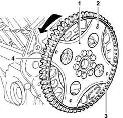
2 Torque converter attachment holes
3 Reluctor ring
4 Starter motor ring gear
The single-piece steel flywheel is bolted to the rear of the crankshaft with nine bolts. The torque converter is attached to the back of the flywheel with four bolts. Bolted to the flywheel is the reluctor ring for the crankshaft position sensor and the starter motor ring gear.
Connecting Rods
The connecting rods are sintered type, one-piece forged rods which feature a fracture-split at the big-end between the connecting rod and the bearing cap. The mating surface of the rod and bearing cap form a rough surface (interference fit) that eliminates the need for centring sleeves. Each matched rod and bearing cap pair is labelled with a pairing code. All of the rods are of one weight class and conform to the double bearing classification, red or blue. One red and one blue bearing shell are fitted to each connecting rod. The red shell is fitted to the bearing cap.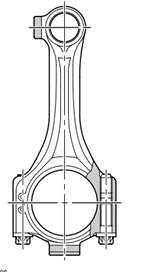
Pistons
The pistons are of short skirt design and “iron-coated” for use with the Alusil block. Each piston has a flat crown surface with a front-facing arrow for installation direction.
The fitting cylinder bank number is inscribed into the piston crown. Each piston is fitted with a couple of compression rings and an oil control ring.
There are not any thermal control strips present in the pistons. The pistons are cooled with specific spray jets, mounted in the crankcase.
Piston Lubrication Jets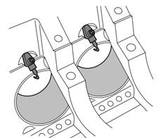
Hook-type nozzles are joined directly with an oil gallery in the crankcase and protected by a couple of screws.
The jets provide lubrication to the cylinder walls,
and to the piston underskirt for cooling the pistons and
lubricating the gudgeon pins and small-end bearings.
Sump
The two-piece aluminium moulded sump, having a fundamental tunnel for the distinctive drive shaft, is bolted to the lower crankcase extension by making use of a rubber metal-backed gasket. The sump is fastened to the lower crankcase extension applying 25 bolts. An oil deflector plate is fixed to the crankcase reinforcing shell at the top of the sump. The sump incorporates a drain plug and a dip-stick guide tube.
Timing Case Covers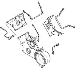
Separate timing case covers are attached to the two-cylinder heads and the crankcase.
The upper timing case covers have ports for the VCC solenoid valves and Camshaft Position (CMP) sensors.
The lower cover has an essential mounting for the alternator which serves as a water jacket.
A drain plug and sealing ring is fitted to the bottom of the mounting. Rubber pre-formed gaskets form seals between the cylinder heads and crankcase and respective timing case covers.
The oil Pump
The oil pump is located in the sump and is attached to Nos 1 and 2 main bearing caps. The oil pump housing and the cover is made using cast aluminium. The gear type oil pump is driven via the crankshaft. The rotor-type pump gives off a regulated pressure of around 4.5 bar. A metal suction pipe gets oil from the sump.
Cylinder Head Components
Cylinder Head Cover
The cylinder head cover is manufactured from magnesium alloy and is secured to the cylinder head with 11 threaded spacers with rubber seals. The right-hand cover consists of an oil filler cap. The cylinder head cover also allows mounting for the coils. The coils are protected by a plastic cover, sealed with a rubber gasket. The cover is retained with two bolts which are covered with protective caps. NOTE: Any harm to the magnesium cover may result in corrosion.
Cylinder Heads 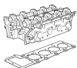
The cross-flow cylinder heads are composed of die-cast aluminium and feature:
- Centrally located spark plugs
- Four valves per cylinder
- Two camshafts
- Bucket tappets coupled with hydraulic valve clearance adjusters
The combustion chambers are machined into the heads, thus assuring more uniform “matched” combustion chambers and compression pressures. The oil distribution flanges are attached to the front end of the cylinder head. The flanges provide a mounting for the VCC solenoids and the advance-retard ports from the solenoids to the intake camshafts.
The cylinder heads for each bank are different lengths due to the offset of the cylinder rows (cylinder bank 1–4 is shorter). NOTE: The cylinder head gasket part numbers are different for the two cylinder banks. The cylinder head is machinable to a limit of 0.3 mm. A repair cylinder head gasket is available and is identified by a small hole beside the 4th and 8th cylinder apertures.
Camshafts
Two solid cast iron camshafts are utilized for each cylinder head. The cams run in five machined bearing surfaces with numbered caps for identification. The camshafts are also marked for identification and incorporate hexagonal machined blocks for timing the cams during installation. For installation and servicing, the camshafts are held in position with locking pins. These pins are implanted into the front camshaft bearing caps on both cylinder heads.
Valves
The inlet and exhaust valves have been organized in a “V” pattern. The valves use single, conical, coil bound shaped valve springs and Hydraulic Valve Adjustment (HVA) tappets and each consists of the following constituents:
Valve x 1 (inlet or exhaust)
Valve stem seal x 1
Valve spring x 1
Valve spring seat x 1
Valve spring cap x 1
Valve collets x 2
Tappet x 1
Hydraulic Valve Adjustment Tappets
Bucket type hydraulic tappets are put to use for the adjustment of the valve clearance. The buckets are self-breathing with a carbon nitride finished cam contact surface.
Primary drive
The primary drive is brought a single roller chain from the crankshaft to the two rubber-coated cam gears. The train is guided by a centrally positioned V-shaped aluminium deflector rail, a straight rail on cylinder bank 5 to 8 and a curved tensioner rail on cylinder bank 1 to 4. Timing chain adjustment is carried out with a hydraulic tensioner mounted on the upper case for cylinders 1 to 4.
Secondary Drive
The secondary drive is from the intake camshaft to the exhaust camshaft by the only roller chain. Chain tension is managed by a hydraulic, spring assisted tensioner that engulfs an oil spray jet. The oil supply for the chain tensioner also supplies the VCC hydraulic units through a pressure control valve.
Ancillary Components and Belt Drive
The ancillary constituents, A/C compressor, alternator, the torsional vibration damper, steering pump and water pump, are driven by the engine crankshaft with the assistance of the ancillary drive belts. The A/C compressor is managed by a separate belt. The belts, which are maintenance-free poly-vee type belts, are automatically pre-loaded by a couple of tensioning spring pots and are routed over deflection pulleys to handle sufficient adhesion about the ancillary pulleys. This ensures the slip-free drive of the ancillary constituents.
Belt Drive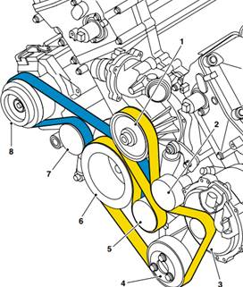
1 Coolant pump
2 Idler pulley
3 Alternator
4 Power assisted steering pump
5 Tensioner pulley
6 Crankshaft pulley
7 Tensioner pulley
8 A/C compressor
Air Intake System
The inlet manifold is a lightweight, one-piece plastic moulding. Fuel is provided by a single fuel rail and managed by a single pressure regulator bolted on the end of the rail. The manifold is acoustically decoupled from the cylinder heads to reduce noise and vibrations. The throttle plate contains a couple of wedges screwed directly to it, these offer a curved zone for an even throttle response during the idle, off-idle transition. The combined out-turn of the mixing plate makes sure that the gasses and vapours are evenly distributed among all the cylinders, which can improve idle quality.
Lubrication
The lubrication system is a wet-sump, pressure fed system that makes the engine sliding surfaces smooth, fritters away heat and soaks up fuel combustion remnant.
Operation
Oil from the sump is drawn up through a fabricated metal pick-up pipe which contains a mesh to filter out any relatively large particles of material which could cause damage to the oil pump. The head of the pick-up is centrally immersed in the sump oil which is delivered to the rotor pump.
Variable Camshaft Control (VCC)
The V8 engine makes use of a VCC (Variable Camshaft Control) system for valve timing on the intake camshaft. While the engine is running the inlet camshafts are continuously adjusted to their optimum position. Both camshafts are simultaneously adjusted to a maximum of 20° of the crankshaft rotational axis. This equalizes to a maximum span of 40° crankshaft rotation.
Cylinder Bank Components
Each cylinder bank consists of the following components:
Cylinder head coupled with oil ports for the VCC system
Control solenoid valve
VCC Transmission and sprockets
Oil distribution flanges
Oil check valve
Camshaft position impulse wheels
Camshaft position sensors
Control Solenoid Valve
The control solenoid valve is fixed with an integral non-return valve and has four ports:
1 Input supply port — engine oil pressure
2 Output retard port — at the back of piston/helical gear (retarded camshaft position)
3 Output advance port — at the back of piston/helical gear (advanced camshaft position)
4 Vent — released oil pressure.
The non-return valve is fitted at the back of the solenoid valve in the cylinder head oil gallery. The non-return valve balances the oil supply in the VCC transmission and oil circuits after the engine is switched off. This brushes off the piston movement when the engine is restarted.
VCC Transmission and Sprockets
The primary and secondary timing chain sprockets are integrated with the self-contained VCC transmission. The regulated adjustment of the crankshaft takes place inside the transmission. The controlled oil pressure activates the piston axially. The helical gear cut of the piston starts in on the helical gears on the interior surface of the transmission and turns around the camshaft to the particular advanced or the retarded angle position.
Three electrical pin contacts are placed on the front surface to corroborate the default maximal retard position by taking services of an ohmmeter. This is needed during assembly and adjustment.
Oil Distribution Flanges
The oil distribution flanges are attached to the front side of each cylinder head. They come up with a mounting location for the VCC solenoids as well as the new-fangled retard oil ports from the solenoids to the inlet camshafts.
Camshafts
Each intake camshaft consists of a couple of oil ports isolated by three sealing rings on their forefront ends. The ports direct pressurized oil from the oil distribution flange to the inner workings of the VCC transmission. Each camshaft has left hand threaded bores in their centres for the attachment of the timing chain sprockets on the exhaust cams and the VCC transmissions for each intake camshaft.
Camshaft Position Impulse Wheels
The camshaft position impulse wheels bring forth camshaft position status to the engine control module through the camshaft position sensors. The uneven placement of the sensor wheel pulse provides the engine control module with the cylinder specific position ID in concurrence with the crankshaft position.
Camshaft Position Sensors
There are a couple of CMP position sensors positioned on the upper timing case covers.
The camshaft position sensors keep tabs on the position of the camshafts to bring into being the ignition timing order, fuel injection stimulation and for accurate Variable Camshaft Control (VCC) camshaft advance-retard timing feedback.
The camshaft position sensor is a hall-effect sensor which turns the battery fed supply on and off. The supply is switched on when the teeth machine positioned onto the camshaft gear goes by the tip of the sensor. The shapes for all the four teeth are different, hence the ECM can figure out the precise position of the camshaft at a given interval of time.